module
18
.png)
The screen you built in S17 works and is entirely white. Every tile the same, because the one table you did not touch is the one that decides colour.
Fixing it takes forty bytes of data and three more CALLs. And it comes with
a genuine surprise: getting the colours right is only half the job, because
something else decides whether you can see them at all.
Every pattern has a matching set of eight colour bytes - one per pattern row. Each byte holds two colours:
So 70h means the shape is colour 7 and everything around it is colour 0.
That is the whole idea, and the useful thing about it is what it is not. The colour does not belong to the cell, or to the screen. It belongs to the pattern. Colour a pattern cyan and every cell showing it is cyan, in one write, wherever they are.
Sixteen values, and every one of them is a real colour you can put on screen.
| Colour | Colour | |||
|---|---|---|---|---|
| 0 | transparent | 8 | medium red | |
| 1 | black | 9 | light red | |
| 2 | medium green | A | dark yellow | |
| 3 | light green | B | light yellow | |
| 4 | dark blue | C | dark green | |
| 5 | light blue | D | magenta | |
| 6 | dark red | E | grey | |
| 7 | cyan | F | white |
Colour 0 is transparent, not black. Black is 1. That distinction is the subject of half this section, so it is worth reading twice.
The colour table is laid out exactly like the pattern table. Same size, same three banks, same eight bytes per entry:
| Patterns | Colours | |
|---|---|---|
| bank 0, rows 0-7 | 0000, high byte 64 |
2000, high byte 96 |
| bank 1, rows 8-15 | 0800, high byte 72 |
2800, high byte 104 |
| bank 2, rows 16-23 | 1000, high byte 80 |
3000, high byte 112 |
Which has a pleasing consequence: the routine you wrote in S17 to load a pattern bank loads a colour bank too. Nothing about it needs changing. Give it a different address and a different forty bytes.
        LD HL,colours
        LD A,96
        CALL bank
        LD HL,colours
        LD A,104
        CALL bank
        LD HL,colours
        LD A,112
        CALL bank
Forty bytes, in the same order as the tiles, eight per pattern:
colours:
        DEFB 0F0h,0F0h,0F0h,0F0h,0F0h,0F0h,0F0h,0F0h   ; 0 blank
        DEFB 040h,040h,040h,040h,040h,040h,040h,040h   ; 1 corner
        DEFB 070h,070h,070h,070h,070h,070h,070h,070h   ; 2 horizontal
        DEFB 0C0h,0C0h,0C0h,0C0h,0C0h,0C0h,0C0h,0C0h   ; 3 vertical
        DEFB 080h,080h,080h,080h,080h,080h,080h,080h   ; 4 spot
Dark blue corners, cyan bars, green sides, red spots. Each byte repeated eight times because each tile is one colour all the way down - and note how obvious it is that they need not be, which is the last exercise.
Add the three CALLs and the forty bytes to S17's program and run it.
Cyan bars along the top and bottom. Green bars down the sides. Red spots filling the middle. And no corners at all - just backdrop where the four corner tiles should be.
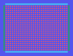
Nothing is wrong with your colour table. The corners are exactly the dark blue you asked for. You cannot see them because the screen behind them is that same dark blue - not a near miss, the identical colour. Colour 4 is what MOS leaves the backdrop set to.
Every tile in that set has 0 in its low nibble, so every unset pixel is
transparent. And transparent means you see the backdrop - a single colour
behind everything, set by the low nibble of register 7:
        LD A,240        ; F0h: low nibble 0
        OUT (9),A
        LD A,135        ; 80h + 7 - register 7
        OUT (9),A
Add that and run it again. The screen is now black, and the blue corners are plainly there - a box outline with an inner square, exactly as designed.
Nothing about the corners changed. The thing behind them did.
So the backdrop is not a background colour in the decorative sense. It is the colour of every transparent pixel on the display, which with this tile set is most of them. Choose it first, and choose your tile colours against it.
Two things follow that are worth keeping.
Transparency is a tool, not an absence. A tile whose low nibble is 0 lets the backdrop through, so changing one register recolours the gaps in every tile at once - a whole-screen colour change for two instructions and no VRAM writes.
And if a tile is invisible, look at the backdrop before you look at the tile.
        ORG 256

        ; --- backdrop first
        LD A,240
        OUT (9),A
        LD A,135
        OUT (9),A

        ; --- patterns
        LD HL,tiles
        LD A,64
        CALL bank
        LD HL,tiles
        LD A,72
        CALL bank
        LD HL,tiles
        LD A,80
        CALL bank

        ; --- colours, same routine
        LD HL,colours
        LD A,96
        CALL bank
        LD HL,colours
        LD A,104
        CALL bank
        LD HL,colours
        LD A,112
        CALL bank

        ; --- the map, as in S17
        LD A,0
        OUT (9),A
        LD A,120
        OUT (9),A

        LD HL,TileMap
        LD BC,768
map:    LD A,(HL)
        OUT (8),A
        INC HL
        DEC BC
        LD A,B
        OR C
        JR NZ,map

        JP $

bank:   LD D,A
        LD A,0
        OUT (9),A
        LD A,D
        OUT (9),A
        LD B,40
copy:   LD A,(HL)
        OUT (8),A
        INC HL
        DJNZ copy
        RET

tiles:
        ; 0 - blank
        DEFB 00000000b,00000000b,00000000b,00000000b
        DEFB 00000000b,00000000b,00000000b,00000000b
        ; 1 - corner
        DEFB 11111111b,10000001b,10111101b,10100101b
        DEFB 10100101b,10111101b,10000001b,11111111b
        ; 2 - horizontal
        DEFB 00000000b,11111111b,00000000b,11111111b
        DEFB 11111111b,00000000b,11111111b,00000000b
        ; 3 - vertical
        DEFB 01011010b,01011010b,01011010b,01011010b
        DEFB 01011010b,01011010b,01011010b,01011010b
        ; 4 - spot
        DEFB 00000000b,00000000b,00111100b,00111100b
        DEFB 00111100b,00111100b,00000000b,00000000b

TileMap:
        DEFB 1,2,2,2,2,2,2,2,2,2,2,2,2,2,2,2,2,2,2,2,2,2,2,2,2,2,2,2,2,2,2,1
        DEFB 3,4,4,4,4,4,4,4,4,4,4,4,4,4,4,4,4,4,4,4,4,4,4,4,4,4,4,4,4,4,4,3
        DEFB 3,4,4,4,4,4,4,4,4,4,4,4,4,4,4,4,4,4,4,4,4,4,4,4,4,4,4,4,4,4,4,3
        DEFB 3,4,4,4,4,4,4,4,4,4,4,4,4,4,4,4,4,4,4,4,4,4,4,4,4,4,4,4,4,4,4,3
        DEFB 3,4,4,4,4,4,4,4,4,4,4,4,4,4,4,4,4,4,4,4,4,4,4,4,4,4,4,4,4,4,4,3
        DEFB 3,4,4,4,4,4,4,4,4,4,4,4,4,4,4,4,4,4,4,4,4,4,4,4,4,4,4,4,4,4,4,3
        DEFB 3,4,4,4,4,4,4,4,4,4,4,4,4,4,4,4,4,4,4,4,4,4,4,4,4,4,4,4,4,4,4,3
        DEFB 3,4,4,4,4,4,4,4,4,4,4,4,4,4,4,4,4,4,4,4,4,4,4,4,4,4,4,4,4,4,4,3
        DEFB 3,4,4,4,4,4,4,4,4,4,4,4,4,4,4,4,4,4,4,4,4,4,4,4,4,4,4,4,4,4,4,3
        DEFB 3,4,4,4,4,4,4,4,4,4,4,4,4,4,4,4,4,4,4,4,4,4,4,4,4,4,4,4,4,4,4,3
        DEFB 3,4,4,4,4,4,4,4,4,4,4,4,4,4,4,4,4,4,4,4,4,4,4,4,4,4,4,4,4,4,4,3
        DEFB 3,4,4,4,4,4,4,4,4,4,4,4,4,4,4,4,4,4,4,4,4,4,4,4,4,4,4,4,4,4,4,3
        DEFB 3,4,4,4,4,4,4,4,4,4,4,4,4,4,4,4,4,4,4,4,4,4,4,4,4,4,4,4,4,4,4,3
        DEFB 3,4,4,4,4,4,4,4,4,4,4,4,4,4,4,4,4,4,4,4,4,4,4,4,4,4,4,4,4,4,4,3
        DEFB 3,4,4,4,4,4,4,4,4,4,4,4,4,4,4,4,4,4,4,4,4,4,4,4,4,4,4,4,4,4,4,3
        DEFB 3,4,4,4,4,4,4,4,4,4,4,4,4,4,4,4,4,4,4,4,4,4,4,4,4,4,4,4,4,4,4,3
        DEFB 3,4,4,4,4,4,4,4,4,4,4,4,4,4,4,4,4,4,4,4,4,4,4,4,4,4,4,4,4,4,4,3
        DEFB 3,4,4,4,4,4,4,4,4,4,4,4,4,4,4,4,4,4,4,4,4,4,4,4,4,4,4,4,4,4,4,3
        DEFB 3,4,4,4,4,4,4,4,4,4,4,4,4,4,4,4,4,4,4,4,4,4,4,4,4,4,4,4,4,4,4,3
        DEFB 3,4,4,4,4,4,4,4,4,4,4,4,4,4,4,4,4,4,4,4,4,4,4,4,4,4,4,4,4,4,4,3
        DEFB 3,4,4,4,4,4,4,4,4,4,4,4,4,4,4,4,4,4,4,4,4,4,4,4,4,4,4,4,4,4,4,3
        DEFB 3,4,4,4,4,4,4,4,4,4,4,4,4,4,4,4,4,4,4,4,4,4,4,4,4,4,4,4,4,4,4,3
        DEFB 1,2,2,2,2,2,2,2,2,2,2,2,2,2,2,2,2,2,2,2,2,2,2,2,2,2,2,2,2,2,2,1
What you should see
A black screen. Blue boxed corners, cyan textured bars top and bottom, green striped bars down both sides, and a grid of red spots through the middle.
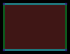
Four colours from forty bytes, and not one of them chosen per cell - every one belongs to a pattern, and the map decides where patterns go.
LD A,240 to LD A,244. The backdrop is dark blue again. Which
tiles disappear, and why those?80h to 81h. The screen does not change at
all, and that is the interesting part: the ground around each spot is now
black ink rather than transparency, and on a black backdrop those look
identical. Now change LD A,240 to LD A,246 and run it again. Everything
else follows the new backdrop and the spots' surroundings refuse to - which
is the difference, made visible.4Fh. Describe what you expect before running
it.F0h to F1h. The blank tiles are all
bits 0, so which nibble matters - and does the screen change?CALLs. What colour is everything, and where did
that come from?18.1 - Your own scheme. Recolour the whole screen by editing only the forty bytes of colour data. Then find a combination that is genuinely unreadable, and say which rule it broke.
18.2 - One write, whole screen. Write a program that draws the screen and then changes register 7 four times with a pause between, so the backdrop cycles. Notice how much changes for two instructions.
18.3 - The palette. Put all sixteen values on screen at once - a solid tile for each, side by side in one row - and check them against the table above. One of the sixteen is not really a colour: it takes whatever the backdrop is, so it will always match one of the other fifteen, and which one is your choice. Work out which value that is, then choose a backdrop that makes the remaining fifteen easy to tell apart.
18.4 - Colour by bank. Give the same pattern a different colour in bank 0, bank 1 and bank 2, then put it in all three thirds of the screen. What does that let you do that a single colour would not?
18.5 - Eight colours in one tile. Each of a pattern's eight rows has its own colour byte. Design a tile that uses all eight differently - a rainbow, a gradient, a sky fading to ground - and predict what you will get before you run it. A solid pattern makes it clearest: eight rows of ink and nowhere for the backdrop to show through.
| What you see | What it means |
|---|---|
| A tile is invisible | Its ink is too close to the backdrop, or both nibbles are the same, or the ink is 0. Check the backdrop before the tile. |
| Everything is white | The colour table was never written. MOS leaves it white on transparent. |
| Colours are right at the top and wrong lower down | Only bank 0 was coloured. All three banks need it, at 96, 104 and 112. |
| A colour appears one tile out | The colour entry for pattern n is at n x 8, like the pattern itself. An extra OUT spills into the next tile's entry. |
| The gaps in the tiles change colour when you did not ask | You changed register 7. It colours every transparent pixel on the display. |
| A black screen and no error | Colon separators. One instruction per line. |
2000, 2800, 3000 - high bytes 96, 104,
112.S19. Sprites. Everything on screen so far is nailed to the 8 x 8 grid, and moving anything means rewriting the map. The VDP will draw up to 32 small pictures anywhere it is told, to the pixel, over the top of all this - moving one costs two bytes, and it turns out you already have 256 shapes to choose from.
This form is protected by reCAPTCHA, and the Google Privacy Policy and Terms of Service apply.
