module
17
.png)
In S16 you put one shape on screen and showed it twice. That is the mechanism. This is the section where it becomes a screen.
By the end you will have a display built entirely from tiles of your own design, laid out by a map you can read as a picture in your own source code - and changing the screen will mean editing that picture, not the program.
There is a price, and it is worth knowing before you pay it: this is the section where the ROM's text output stops working. More on that at the end.
S16 asked you to send a diamond to a cell in row 9, and said it would not appear. Here is why.
The pattern table is not one table. It is three.
Graphics II divides the screen into thirds, and each third reads its patterns from a different 2048-byte block:
| Screen rows | Pattern bank | Address | High byte to send |
|---|---|---|---|
| 0 to 7 | bank 0 | 0000-07FF |
64 |
| 8 to 15 | bank 1 | 0800-0FFF |
72 |
| 16 to 23 | bank 2 | 1000-17FF |
80 |
Pattern 34 in bank 0 and pattern 34 in bank 1 are different eight-byte patterns at different addresses. A cell in row 1 asking for pattern 34 gets the first; a cell in row 9 asking for pattern 34 gets the second. Your diamond went into bank 0, so the row 9 cell showed whatever bank 1 happened to hold.
This is the cost of every cell owning its own colours as well as its own pattern: the pattern space triples to match, three blocks of 256 instead of one.
And 768 is not a coincidence. The screen is 32 cells across and 24 down, which is 768 cells - exactly as many as the three banks hold patterns between them, one each, with none left over. That is what makes a bitmap possible at all: every one of the 768 cells on screen can own a genuinely different pattern.
So MOS's bitmap is Graphics II used exactly as intended. Your tile map is the other thing the mode is good for - few shapes, heavily reused - and the three banks are the price you pay for it.
The rule that follows is simple: a pattern must exist in every bank where you intend to use it. And the simplest way to satisfy that is to put every tile in every bank, which costs three lines of code and a few hundred bytes of VRAM you are not otherwise using.
Five tiles make a bordered screen. Design them the way S16 designed the diamond - on squared paper, then read off the rows:
tiles:
        ; 0 - blank
        DEFB 00000000b,00000000b,00000000b,00000000b
        DEFB 00000000b,00000000b,00000000b,00000000b
        ; 1 - corner
        DEFB 11111111b,10000001b,10111101b,10100101b
        DEFB 10100101b,10111101b,10000001b,11111111b
        ; 2 - horizontal
        DEFB 00000000b,11111111b,00000000b,11111111b
        DEFB 11111111b,00000000b,11111111b,00000000b
        ; 3 - vertical
        DEFB 01011010b,01011010b,01011010b,01011010b
        DEFB 01011010b,01011010b,01011010b,01011010b
        ; 4 - spot
        DEFB 00000000b,00000000b,00111100b,00111100b
        DEFB 00111100b,00111100b,00000000b,00000000b
Forty bytes. Five patterns, numbered 0 to 4, and because they are laid out one after another in that order, the whole set can be sent to the VDP as one block - address the start of pattern 0 and stream all forty bytes. The VDP advances its own address, so patterns 1 to 4 land where they should.
One subroutine does a bank:
; copy 40 bytes from (HL) into pattern 0 onwards of one bank.
; A holds the bank's high byte: 64, 72 or 80.
bank:   LD D,A
        LD A,0
        OUT (9),A       ; low byte 0 - pattern 0
        LD A,D
        OUT (9),A
        LD B,40         ; five patterns of eight bytes
copy:   LD A,(HL)
        OUT (8),A
        INC HL
        DJNZ copy
        RET
That is S11's pointer walk feeding OUT (8),A, with S13's DJNZ counting.
Nothing in it is new.
And all three banks:
        LD HL,tiles
        LD A,64
        CALL bank
        LD HL,tiles
        LD A,72
        CALL bank
        LD HL,tiles
        LD A,80
        CALL bank
HL is reloaded each time because bank walks it to the end.
Now the part worth the section. The screen is 32 cells across and 24 down, and the name table is those 768 cells in order. So write the screen as data:
TileMap:
        DEFB 1,2,2,2,2,2,2,2,2,2,2,2,2,2,2,2,2,2,2,2,2,2,2,2,2,2,2,2,2,2,2,1
        DEFB 3,4,4,4,4,4,4,4,4,4,4,4,4,4,4,4,4,4,4,4,4,4,4,4,4,4,4,4,4,4,4,3
        ; ... twenty more rows like that ...
        DEFB 3,4,4,4,4,4,4,4,4,4,4,4,4,4,4,4,4,4,4,4,4,4,4,4,4,4,4,4,4,4,4,3
        DEFB 1,2,2,2,2,2,2,2,2,2,2,2,2,2,2,2,2,2,2,2,2,2,2,2,2,2,2,2,2,2,2,1
Twenty-four lines of thirty-two numbers. Corner, thirty horizontals, corner. Then twenty-two rows of vertical, thirty spots, vertical. Then the top row again.
You can see the screen in the source. That is not a small thing. Squint at those numbers and the border is visible in the shape of the data, and to change the screen you edit the picture rather than the program.
Getting it there is the same loop as always:
        LD A,0
        OUT (9),A
        LD A,120        ; 40h + 38h - the name table
        OUT (9),A

        LD HL,TileMap
        LD BC,768
map:    LD A,(HL)
        OUT (8),A
        INC HL
        DEC BC
        LD A,B
        OR C
        JR NZ,map
768 is too many for DJNZ, which counts in a single byte, so the count goes
in BC. And DEC BC does not set the flags - so the test is LD A,B /
OR C, which is zero only when both halves are. That idiom will come up
whenever you count past 255.
        ORG 256

        ; --- the five tiles into each of the three banks
        LD HL,tiles
        LD A,64
        CALL bank
        LD HL,tiles
        LD A,72
        CALL bank
        LD HL,tiles
        LD A,80
        CALL bank

        ; --- the screen, from the map
        LD A,0
        OUT (9),A
        LD A,120
        OUT (9),A

        LD HL,TileMap
        LD BC,768
map:    LD A,(HL)
        OUT (8),A
        INC HL
        DEC BC
        LD A,B
        OR C
        JR NZ,map

        JP $

bank:   LD D,A
        LD A,0
        OUT (9),A
        LD A,D
        OUT (9),A
        LD B,40
copy:   LD A,(HL)
        OUT (8),A
        INC HL
        DJNZ copy
        RET

tiles:
        ; 0 - blank
        DEFB 00000000b,00000000b,00000000b,00000000b
        DEFB 00000000b,00000000b,00000000b,00000000b
        ; 1 - corner
        DEFB 11111111b,10000001b,10111101b,10100101b
        DEFB 10100101b,10111101b,10000001b,11111111b
        ; 2 - horizontal
        DEFB 00000000b,11111111b,00000000b,11111111b
        DEFB 11111111b,00000000b,11111111b,00000000b
        ; 3 - vertical
        DEFB 01011010b,01011010b,01011010b,01011010b
        DEFB 01011010b,01011010b,01011010b,01011010b
        ; 4 - spot
        DEFB 00000000b,00000000b,00111100b,00111100b
        DEFB 00111100b,00111100b,00000000b,00000000b

TileMap:
        DEFB 1,2,2,2,2,2,2,2,2,2,2,2,2,2,2,2,2,2,2,2,2,2,2,2,2,2,2,2,2,2,2,1
        DEFB 3,4,4,4,4,4,4,4,4,4,4,4,4,4,4,4,4,4,4,4,4,4,4,4,4,4,4,4,4,4,4,3
        DEFB 3,4,4,4,4,4,4,4,4,4,4,4,4,4,4,4,4,4,4,4,4,4,4,4,4,4,4,4,4,4,4,3
        DEFB 3,4,4,4,4,4,4,4,4,4,4,4,4,4,4,4,4,4,4,4,4,4,4,4,4,4,4,4,4,4,4,3
        DEFB 3,4,4,4,4,4,4,4,4,4,4,4,4,4,4,4,4,4,4,4,4,4,4,4,4,4,4,4,4,4,4,3
        DEFB 3,4,4,4,4,4,4,4,4,4,4,4,4,4,4,4,4,4,4,4,4,4,4,4,4,4,4,4,4,4,4,3
        DEFB 3,4,4,4,4,4,4,4,4,4,4,4,4,4,4,4,4,4,4,4,4,4,4,4,4,4,4,4,4,4,4,3
        DEFB 3,4,4,4,4,4,4,4,4,4,4,4,4,4,4,4,4,4,4,4,4,4,4,4,4,4,4,4,4,4,4,3
        DEFB 3,4,4,4,4,4,4,4,4,4,4,4,4,4,4,4,4,4,4,4,4,4,4,4,4,4,4,4,4,4,4,3
        DEFB 3,4,4,4,4,4,4,4,4,4,4,4,4,4,4,4,4,4,4,4,4,4,4,4,4,4,4,4,4,4,4,3
        DEFB 3,4,4,4,4,4,4,4,4,4,4,4,4,4,4,4,4,4,4,4,4,4,4,4,4,4,4,4,4,4,4,3
        DEFB 3,4,4,4,4,4,4,4,4,4,4,4,4,4,4,4,4,4,4,4,4,4,4,4,4,4,4,4,4,4,4,3
        DEFB 3,4,4,4,4,4,4,4,4,4,4,4,4,4,4,4,4,4,4,4,4,4,4,4,4,4,4,4,4,4,4,3
        DEFB 3,4,4,4,4,4,4,4,4,4,4,4,4,4,4,4,4,4,4,4,4,4,4,4,4,4,4,4,4,4,4,3
        DEFB 3,4,4,4,4,4,4,4,4,4,4,4,4,4,4,4,4,4,4,4,4,4,4,4,4,4,4,4,4,4,4,3
        DEFB 3,4,4,4,4,4,4,4,4,4,4,4,4,4,4,4,4,4,4,4,4,4,4,4,4,4,4,4,4,4,4,3
        DEFB 3,4,4,4,4,4,4,4,4,4,4,4,4,4,4,4,4,4,4,4,4,4,4,4,4,4,4,4,4,4,4,3
        DEFB 3,4,4,4,4,4,4,4,4,4,4,4,4,4,4,4,4,4,4,4,4,4,4,4,4,4,4,4,4,4,4,3
        DEFB 3,4,4,4,4,4,4,4,4,4,4,4,4,4,4,4,4,4,4,4,4,4,4,4,4,4,4,4,4,4,4,3
        DEFB 3,4,4,4,4,4,4,4,4,4,4,4,4,4,4,4,4,4,4,4,4,4,4,4,4,4,4,4,4,4,4,3
        DEFB 3,4,4,4,4,4,4,4,4,4,4,4,4,4,4,4,4,4,4,4,4,4,4,4,4,4,4,4,4,4,4,3
        DEFB 3,4,4,4,4,4,4,4,4,4,4,4,4,4,4,4,4,4,4,4,4,4,4,4,4,4,4,4,4,4,4,3
        DEFB 3,4,4,4,4,4,4,4,4,4,4,4,4,4,4,4,4,4,4,4,4,4,4,4,4,4,4,4,4,4,4,3
        DEFB 1,2,2,2,2,2,2,2,2,2,2,2,2,2,2,2,2,2,2,2,2,2,2,2,2,2,2,2,2,2,2,1
What you should see
A bordered screen. Boxed corners, textured bars along the top and bottom, striped bars down both sides, and a regular grid of spots filling the middle - all the way down, through all three thirds.
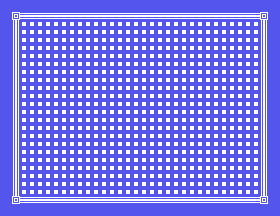
JP $ at the end holds it there. Press Restart when you have looked at it.
You will have noticed. The border, the corners, the spots - all the same colour, on the blue the screen already was.
That is not a limitation of tiles. A pattern's colours come from a table this program never touches, and MOS left every entry in it set to white on transparent - which is why every tile is white, and why the blue shows through wherever a pattern's bits are 0.
One table, and you get a border in one colour and an interior in another. That is the next section.
The screen is yours now, and that means it is not MOS's any more.
The name table used to be a list of ascending numbers, which is what made the
display a bitmap and what let the ROM draw characters into it. It is now a
tile map. RST 8 / DEFB 158 can no longer put readable text on the
screen - it will still run, still compute addresses, still write bytes, and
what comes out will be nonsense, because it is writing pixels into a pattern
that hundreds of cells are all sharing. Print one character on the screen you
just built and every cell in that third showing the same tile changes with it.
From here a program that wants text has to provide it itself. That is much less work than it sounds, because the machine left something behind on its way out - which is the next heading.
This is the one-way door of the course. Everything before it used the ROM; everything after it does not.
MOS cannot write text on your screen any more. But its font is still
sitting in video memory, untouched: the takeover rewrote the three pattern
banks and the name table, and never went near the 2048 bytes at 6144. Ninety-
six letter shapes, already drawn, eight bytes each, at 6144 + code * 8.
You cannot select them where they are. The name table picks tiles out of the three banks, and nothing else in the machine points at an arbitrary address and says "display that". But a glyph is not a special object. It is eight ordinary bytes with a letter drawn in the top six bits of each - and bytes can be copied.
Every trip through ports 8 and 9 so far has been a write. Reading is the same
two-byte address setup with one change: leave the 64 off the second byte.
Then IN A,(8) fetches a byte, and the address steps forward on its own,
exactly as it does when writing:
      LD A,0
      OUT (9),A          ; low byte of the address
      LD A,25            ; high byte - no 64 added: this is a read
      OUT (9),A
      IN A,(8)           ; first byte arrives in A
      IN A,(8)           ; ...but see below before doing this
One care. Keep an ordinary loop around the IN - one that stores each byte
and counts - rather than stripping it down to bare INs in a row. If a read
ever hands you bytes that are not the ones you asked for, that loop is the
first thing to put back.
        ORG 256

        ; --- blank tile 0 in every bank
        LD A,64
        CALL zero8
        LD A,72
        CALL zero8
        LD A,80
        CALL zero8

        ; --- clear the name table: every cell shows tile 0
        LD A,0
        OUT (9),A
        LD A,120
        OUT (9),A
        LD BC,768
clr:    LD A,0
        OUT (8),A
        DEC BC
        LD A,B
        OR C
        JR NZ,clr

        ; --- read glyphs 32-127 out of the font at 6400
        LD A,0
        OUT (9),A
        LD A,25            ; high byte of 6400 - no 64: a read
        OUT (9),A
        LD HL,buffer
        LD BC,768          ; 96 glyphs x 8 bytes
rd:     IN A,(8)
        LD (HL),A
        INC HL
        DEC BC
        LD A,B
        OR C
        JR NZ,rd

        ; --- write them into bank 0 at 256, which is 32 x 8:
        ;     every glyph lands at tile number = character code
        LD A,0
        OUT (9),A
        LD A,65            ; 64 + high byte of 256
        OUT (9),A
        LD HL,buffer
        LD BC,768
wr:     LD A,(HL)
        OUT (8),A
        INC HL
        DEC BC
        LD A,B
        OR C
        JR NZ,wr

        ; --- print: copy the string's bytes into the name table
        LD A,34            ; row 1, column 2 = 1*32 + 2
        OUT (9),A
        LD A,120
        OUT (9),A
        LD HL,message
        LD B,12
pr:     LD A,(HL)
        OUT (8),A
        INC HL
        DJNZ pr

        JP $

        ; --- eight zero bytes to the bank whose high byte is in A
zero8:  LD D,A
        LD A,0
        OUT (9),A
        LD A,D
        OUT (9),A
        LD A,0
        LD B,8
z8:     OUT (8),A
        DJNZ z8
        RET

message:
        DEFM "SCORE 000100"
buffer:
        DEFS 768
What you should see: SCORE 000100, white, near the top of an otherwise
empty screen.
Look at what printing has just become. The glyphs went in at tile number =
character code, so tile 83 is S and tile 48 is 0 - and printing a
string is nothing but copying its bytes into the name table. Twelve bytes,
twelve characters, done. When the ROM printed a character it moved sixteen
bytes of pixels through these same two ports; you moved one. This is the
other half of S17's trade: you gave up the ROM's forty columns, and got back
the instant text that a screen made of tiles was always capable of.
3,4,4,...,4,3 to
3,0,0,...,0,3. What fills that row now, and why is pattern 0 blank rather
than black?4 in the middle of the map to a 1. Find it on screen.CALL bank - the one with 80. The bottom third goes
completely empty rather than turning to rubbish. Work out what those cells
are showing, and why it comes out blank rather than as a mess.LD A,64 to LD A,0 in the first CALL bank. The tiles do not
arrive. Which bit did you drop, and what did the VDP think you were asking
for?LD B,40 to LD B,8. The screen goes entirely empty. Which tile did
survive, and why does the answer look like nothing at all?RST 8 / DEFB 158 with a character in A at the end, before the
JP $. Look carefully at what happens to the screen.17.1 - Your own border. Redesign all five tiles and rebuild the screen. Keep the map exactly as it is - only the forty bytes of tile data change.
17.2 - A room. Draw a map with a doorway in one wall and a block of solid tiles somewhere in the middle. This is a game level, and you have just written the level format.
17.3 - Two screens. Put a second map in memory and a routine that takes a
map address in HL and draws it. Then draw one, wait for a key with call 156,
and draw the other. That is screen switching.
17.4 - Economise. Corners and horizontals only appear in rows 0 and 23, which are in banks 0 and 2. Rewrite the bank loading so bank 1 gets only the tiles it needs, and count the bytes you saved. Then decide whether you would keep the change - and say why.
17.5 - Draw one cell. Write a subroutine that takes a row in B, a column
in C and a tile number in A, and writes that one name table entry. You
will need row * 32 + col, and 32 is a power of two, so no multiply
instruction is required.
17.6 - A moving dot. Using 17.5, put a tile at one cell, wait, blank it, and put it at the next cell along. Repeat across the screen. It will be jerky and it will flicker, and both of those are problems the following sections solve - but it moves.
17.7 - A score on the floor. Copy just the digits - codes 48 to 57, eighty
bytes - into the bottom third's bank, and print 000100 on the screen's
last row. Two things have to change from the example: which bank the glyphs
land in, and where in the name table the string goes.
| What you see | What it means |
|---|---|
| A black screen and no error at all | Colon separators. LD A,n : OUT (8),A assembles to one wrong byte with no complaint. One instruction per line. |
| The top third is right and the rest is rubbish | Only bank 0 was loaded. Every tile needs to be in every bank it is used in. |
| Nothing arrives in a bank | The high byte needs 40h added. 64, 72 and 80 already include it; 0, 8 and 16 do not. |
| The whole display corrupts | A high byte of 80h or more, which makes it a register write instead of an address. |
| The map is shifted by a few cells | 32 cells per row, not 40. Text was 40 columns wide; tiles are not. |
| Text printed afterwards is unreadable | Expected. The name table is a tile map now, and the ROM's text output cannot work against it. |
| Borrowed glyphs come back as rubbish | The second address byte of the read got 64 added, which made it a write and read nothing. Reads take the high byte bare. |
| Borrowed glyphs are fine on top, missing lower down | The copy went into one bank. Same rule as any tile. |
0000, 0800, 1000, high bytes
64, 72 and 80 - serving screen rows 0-7, 8-15 and 16-23. A pattern must
exist in every bank it is used in.r * 32 + c.DEFB rows is a screen you can read in your own source,
and editing it changes the display without touching the program.BC, tested with LD A,B / OR C, because DEC BC
does not set the flags.S18. Colour. Your screen works and it is entirely one colour. The table
that fixes that sits at 2000, laid out exactly like the patterns - so the
routine you just wrote loads it too. Getting the colours right turns out to be
only half the job.
This form is protected by reCAPTCHA, and the Google Privacy Policy and Terms of Service apply.
