module
6
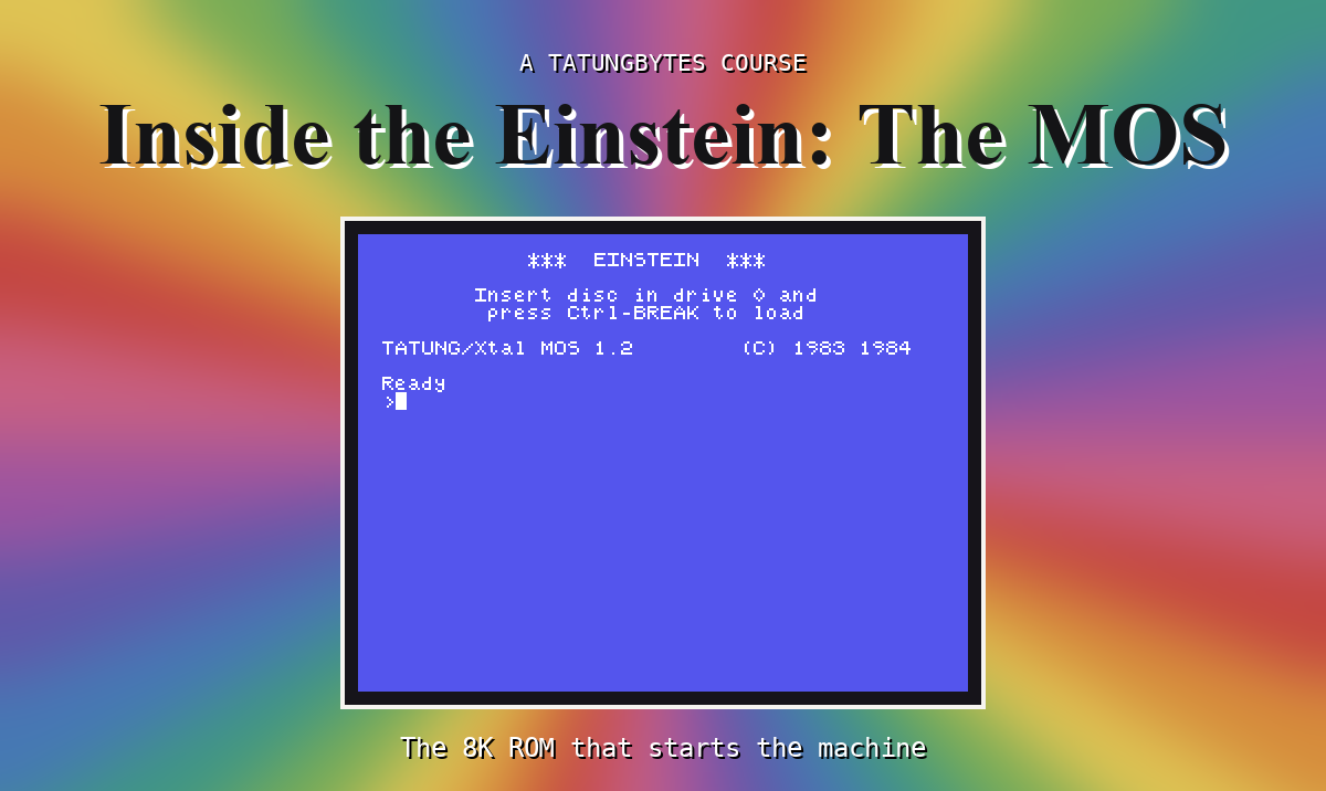
From the first instruction to the word Ready, the heart of the work is about 150 bytes of code. In that time it has to turn a box of chips with empty memory into a machine that can run your program and answer its calls. This section reads that code.
l0000h:
        ld hl,08000h            ;0000
        ld de,08001h            ;0003
        jr l0040h               ;0006
...
l0040h:
        ld bc,07fffh            ;0040
        ld (hl),c               ;0043
        ldir                    ;0044
        ld hl,08000h            ;0046
        ld b,h                  ;0049
        ldir                    ;004a
The first job is to put memory into a known state. LD (HL),C writes FFh (the low byte of 7FFFh) at 8000h, and LDIR with HL one behind DE copies it forward, byte after byte, all the way to the top of memory. The second LDIR copies the top half down over the bottom half. The ROM is switched in the whole time, but a write to the bottom 32K goes to the RAM underneath, so when it finishes, RAM everywhere reads FFh.
This is a classic way to fill memory on a Z80: write one byte, then copy the block onto itself shifted by one. It costs three instructions.
        ld hl,SCINIT            ;0058
        ld de,0fb00h            ;005b
        ld c,046h               ;005e
        ldir                    ;0060
        ld hl,ZDFVCT            ;0062
        ld de,l0000h            ;0065
        ld c,00bh               ;0068
        ldir                    ;006a
        ld de,0fc09h            ;006c
        ld c,084h               ;006f
        ldir                    ;0071
Three blocks of the ROM go to RAM:
| From the ROM | To RAM | Size | What is in it |
|---|---|---|---|
SCINIT, 0FF0h | FB00h | 46h bytes | the interrupt vector table, small routines, and starting values for the MOS's variables - including, at FB3Ah, the address of its table of calls (S8) |
ZDFVCT, 1036h | 0000h | 0Bh bytes | the bottom of RAM - including, at 0008h, a JP FC22h |
ZBANKZ, 1041h | FC09h | 84h bytes | code: RST 8's way in when RAM is switched in (FC22h), its way out (FC40h), and the once-a-second clock (FC47h) |
Now remember S4's third rule: anything that must always be reachable has to live in the top half, or be present in both memories at the same address. This copy is that rule in action.
RST 8 jumps to 0008h - in RAM. So the MOS has put a jump there, at the same address as its own RST 8 entry in the ROM.The first block holds values as well as code, and that is the other reason to copy: a ROM cannot be written to. A value copied into RAM can be changed later. The address at FB3Ah is one such value; S8 shows the MOS reading it on every call.
        ld hl,0fb8ch            ;0073
        ld b,006h               ;0076
l0078h:
        ld (hl),030h            ;0078
        inc hl                  ;007a
        djnz l0078h             ;007b
INITM:
        ld sp,0fcffh            ;007d
l0080h:
        ld a,0fbh               ;0080
        ld i,a                  ;0082
...
        im 2                    ;0090
...
        rst 8                   ;0095
        defb 0bch               ;0096
'0': the clock, held as the digits 000000, hours, minutes and seconds. S12 shows them counting.I is set to FBh and the Z80 put in interrupt mode 2, in which an interrupting chip supplies the low byte of an address and I the high byte. With I = FBh, every interrupt's address is looked up in the vector table at FB00h-FB13h, which the first copy put there. S12 follows one.RST 8 call: to itself. From here on, start-up uses its own calls, just as your programs do.INITM, at 007Dh, matters later. Starting there skips the memory fill and the copies and goes straight on to redraw the start-up screen - a restart rather than a reset. S7 shows a way to get there.
You cannot watch start-up happen, but you can check its work. The monitor's T command shows memory as your programs see it - RAM. At the prompt, type:
T FC22 FC29
then, separately:
T 0008 000A
What you should see
>T FC22 FC29
FC22 22 79 FB E1 F5 7E 23 E3 ...
>T 0008 000A
0008 C3 22 FC ...
(The characters at the end of each line are those bytes shown as characters; here they are not meaningful.)
The first line is code at FC22h, in RAM. In your source, find ZBANKZ and count 19h bytes on, to 105Ah - the same eight bytes are there. The second is the RAM under the ROM at 0008h: C3 22 FC, which is JP FC22h.
Start-up fills memory, then copies three pieces of the ROM into RAM: a JP FC22h at 0008h, code in the always-present top half at FC09h, and the MOS's variables at FB00h. That copy is how the MOS stays reachable when RAM is switched in. It then zeroes the clock, sets the stack at FCFFh and turns on interrupt mode 2 with its table at FB00h.
S7 follows an RST 8 from your program all the way in and back out.
This form is protected by reCAPTCHA, and the Google Privacy Policy and Terms of Service apply.
