module
8
In the assembly course's S19 you met the TC-01's hard limit: four sprites on any one line, and a fifth simply isn't drawn. Every game designed around it. Invaders came in rows of four, or flickered.
The 256 doubles that. In its sprite mode 2 eight sprites share a line. This section switches it on over MOS's own screen, moves the tables to where the mode needs them, and marches eight invaders across one line, with a missile flying up through them to show what happens to the ninth.
The video chip has two kinds of sprite. Sprite mode 1 is the TC-01's: four a line, one colour each, Y = 208 ends the list. It is what you get in Graphics II, and the TC-01's sprite rules carry over to it.
Sprite mode 2 comes with the new screen modes. The simplest of them is Graphics 3, register 0 = 04h instead of Graphics II's 02h. Its tiles are Graphics II's: switch to it over MOS's screen and the text stays just as it was. The sprites are what changes. In sprite mode 2:
One more difference matters if you write long runs to video memory. In Graphics II a run of writes wraps round at the end of its 16K page. In Graphics 3 it carries on into the next one.
Set R#0 to 04h and leave everything else as MOS has it, and you don't get eight sprites. You get a diagonal staircase of rubbish characters down the screen. To see why, you need the rule sprite mode 2 uses to find its tables.
The attribute table is where R#5 and R#11 say:
attribute address = (R#5 AND FCh) x 80h + R#11 x 8000h
Bits 1 and 0 of R#5 are ignored. R#11 is new: it adds 32K at a time, so the table can be anywhere in the 128K.
The colour table has no register of its own. It is the attribute address with bit 9 cleared. When bit 9 of the attribute address is 1 (R#5 bit 2 set), that puts the colour table exactly 512 bytes below the attributes: 32 sprites times 16 lines. When bit 9 is already 0, the chip takes the attribute table itself as the colours. So always write R#5 with its bottom three bits set, ...111, and leave 512 bytes free below the attribute table.
Now MOS's value. MOS leaves R#5 = 76h, for its attribute table at 3B00h. In sprite mode 2, 76h AND FCh is 74h, and 74h x 80h is 3A00h. The colour table is 3A00h with bit 9 cleared: 3800h. Both land in MOS's name table, which runs from 3800h to 3AFFh. The chip reads the screen's character codes as sprite positions and colours, and the staircase is what that looks like.
The 256 has 128K of video memory and MOS uses the first 16K (S5). Page 2, 8000h-BFFFh, is empty at start-up, so this section puts all three sprite tables there, out of MOS's way:
| Table | Address | Register | Size |
|---|---|---|---|
| Colours | 9C00h | (512 below the attributes) | 32 x 16 = 512 bytes |
| Attributes | 9E00h | R#5 = 3Fh, R#11 = 01h | 32 x 4 = 128 bytes |
| Patterns | A000h | R#6 = 14h | 256 x 8 = 2K |
Check the sums. 3Fh AND FCh is 3Ch; 3Ch x 80h is 1E00h; R#11 = 1 adds 8000h: 9E00h. Bit 9 of 9E00h is set, so the colours are at 9C00h. R#6 places the patterns at R#6 x 800h, and in sprite mode 2 it has six bits to do it with, enough for the whole 128K: 14h x 800h is A000h.
To write there you select page 2 with R#14 = 2 and then give the address's low 14 bits in the usual way (S5). Everything costs 2.6K of video memory that MOS never sees.
In sprite mode 2, bit 6 of status register 0, the "too many sprites on a line" bit you met in S3, does a job for the ninth sprite: it is set when nine or more sprites fall on one line, and bits 4-0 hold the number of the ninth sprite, the first one that didn't get drawn. Only trust those five bits in a read that has bit 6 set.
Reading status register 0 clears the flag, and that is the catch with S7's heartbeat. Its handler reads port 9 once a frame, to clear the frame interrupt, and keeps just that one read in STATUS. To be sure of the ninth sprite's number you want the first read that has bit 6 set. So this section's program goes back to polling the frame flag, as in the assembly course's S26, with interrupts off. It reads port 9 over and over until bit 7 rises, and keeps what every read said.
nextf:  LD C, 0             ; all the bits seen this frame
        LD D, 0             ; the first read with bit 6
nf1:    IN A, (9)
        LD E, A
        OR C
        LD C, A
        BIT 6, E
        JR Z, nf2
        LD A, D
        OR A
        JR NZ, nf2
        LD D, E             ; keep it: its bits 4-0 are the number
nf2:    BIT 7, E            ; the frame flag?
        JR Z, nf1
        RET
Remember from S3 that the first read after your program starts can show bit 6 already set. Read port 9 once at the start and throw it away.
The TC-01 stopped at the first sprite whose Y was 208. Sprite mode 2 stops at Y = 216 instead. 208 is just a position below the screen, and the chip carries on to the next entry. A TC-01 habit of writing 208 after your last sprite does nothing here, and the chip goes on through the other 31 entries, whatever is in them.
There is also a switch for all of them at once: bit 1 of register 8 (SPD). Set it and every sprite disappears. Clear it and they come back, with nothing in the tables changed. MOS leaves R#8 = 08h, so 0Ah hides the sprites and 08h brings them back.
s08-invaders.asm: eight invaders in one row, marching left and right, and a missile climbing up through them. In any frame where the missile makes a ninth sprite on a line, the border takes the ninth sprite's number as its colour. After 512 frames, about ten seconds, the program puts MOS's screen back.
The attribute table lives in RAM, at att, and goes to video memory whole at the start of every frame, so all nine sprites move together. The 37 bytes, nine sprites and the end mark, take one OTIR.
; S8: eight invaders on one line, in Graphics 3 (sprite mode 2).
;
; A row of eight 16x16 invaders marches left and right across one line.
; A ninth sprite, a missile, climbs up the screen and through the row.
; Each frame the program keeps every status byte it reads; if the
; ninth-sprite flag was set, the border takes the ninth sprite's number
; as its colour. After 512 frames (about 10 seconds) it puts MOS's
; screen back and returns.
;
; The sprite tables live in VRAM page 2 (R#14 = 2, 8000h-BFFFh):
;   patterns   A000h  (R#6 = 14h)
;   colours    9C00h  (the attribute address with A9 cleared)
;   attributes 9E00h  (R#5 = 3Fh, R#11 = 01h)

        ORG 256

        DI                      ; we poll the frame flag: no interrupts
        IN A, (9)               ; throw away the first status read

; --- the patterns: invader (0-3) and missile (4-7), 64 bytes at A000h
        LD HL, 0A000h
        CALL vaddr
        LD HL, pats
        LD BC, 64*256+8         ; B = 64 bytes, C = port 8
        OTIR

; --- the colour table at 9C00h: 16 bytes a sprite, one per line
        LD HL, 9C00h
        CALL vaddr
        LD HL, colours          ; nine sprites' colours
        LD D, 9
col1:   LD A, (HL)              ; this sprite's colour...
        INC HL
        LD B, 16
col2:   OUT (8), A              ; ...on all 16 of its lines
        DJNZ col2
        DEC D
        JR NZ, col1

; --- Graphics 3, and the sprite tables moved
        LD HL, g3regs
        CALL setregs
        CALL sendatt            ; first positions, before anything shows

; --- the game loop: one pass a frame
loop:   CALL nextf              ; wait for the frame
        LD A, D                 ; D = the read with the ninth-sprite flag
        LD B, 0F4h              ; none: MOS's backdrop, colour 4
        OR A
        JR Z, border
        AND 0Fh                 ; bits 4-0: the ninth sprite's number...
        OR 0F0h                 ; ...becomes the backdrop colour
        LD B, A
border: LD A, B
        LD B, 7
        CALL setreg

        CALL sendatt            ; last frame's moves, sent in one go
        CALL march              ; then work out this frame's
        CALL climb

        LD HL, (frames)
        INC HL
        LD (frames), HL
        LD A, H
        CP 2                    ; 512 frames?
        JR C, loop

; --- back to MOS
        LD HL, mosregs
        CALL setregs
        EI
        RST 8
        DEFB 0BEh               ; MOS: clear to its 40-column screen
        RET

; --- march: move the invaders one pixel; turn round at either end
march:  LD A, (step)
        LD C, A                 ; C = +1 or -1
        LD A, (att+1)           ; the first invader's X
        ADD A, C
        CP 40                   ; at the right-hand end?
        JR Z, turn
        OR A                    ; at the left-hand end?
        JR NZ, mv
turn:   LD B, A
        LD A, C
        NEG
        LD (step), A
        LD A, B
mv:     LD HL, att+1            ; set eight X's, 28 pixels apart
        LD DE, 4
        LD B, 8
mv1:    LD (HL), A
        ADD A, 28
        ADD HL, DE
        DJNZ mv1
        RET

; --- climb: move the missile up a line; back to the bottom at the top
climb:  LD HL, att+32           ; sprite 8's Y
        DEC (HL)
        LD A, (HL)
        CP 10
        RET NZ
        LD (HL), 170
        RET

; --- sendatt: copy the attribute table from RAM to 9E00h
sendatt:
        LD HL, 9E00h
        CALL vaddr
        LD HL, att
        LD BC, 37*256+8         ; 9 sprites of 4 bytes, and the end mark
        OTIR
        RET

; --- nextf: read the status until the frame flag is set.
; Returns C = every status bit seen since the last call, and D = the
; first read with bit 6 set (the only one whose bits 4-0 we trust), or 0.
nextf:  LD C, 0
        LD D, 0
nf1:    IN A, (9)
        LD E, A                 ; this read
        OR C
        LD C, A                 ; add its bits to the rest
        BIT 6, E
        JR Z, nf2               ; no ninth sprite in this read
        LD A, D
        OR A
        JR NZ, nf2              ; already have one
        LD D, E                 ; keep it
nf2:    BIT 7, E                ; the frame flag?
        JR Z, nf1
        RET

; --- vaddr: set the VRAM write address HL, in page 2 (8000h-BFFFh)
vaddr:  LD A, 2
        LD B, 14
        CALL setreg             ; R#14 = 2
        LD A, L
        OUT (9), A
        LD A, H
        AND 3Fh
        OR 64
        OUT (9), A
        RET

; --- setreg: write A to register B
setreg: OUT (9), A
        LD A, B
        OR 128
        OUT (9), A
        RET

; --- setregs: register, value pairs from HL, ending with FFh
setregs:
        LD B, (HL)
        INC HL
        LD A, (HL)
        INC HL
        CALL setreg
        LD A, (HL)
        CP 0FFh
        JR NZ, setregs
        RET

g3regs: DEFB 0, 04h             ; Graphics 3: Graphics II with sprite mode 2
        DEFB 5, 3Fh, 11, 01h    ; attributes 9E00h, colours 9C00h
        DEFB 6, 14h             ; patterns A000h
        DEFB 1, 0C2h            ; display on, 16x16 sprites, no interrupt
        DEFB 0FFh
mosregs: DEFB 0, 02h, 1, 0C0h, 5, 76h, 11, 00h, 6, 03h, 14, 0
        DEFB 7, 0F4h, 8, 08h    ; MOS's backdrop, and R#8 as MOS leaves it
        DEFB 0FFh

frames: DEFW 0
step:   DEFB 1

colours: DEFB 2, 3, 5, 7, 10, 11, 13, 14    ; the eight invaders
        DEFB 15                             ; the missile

; the attribute table, kept in RAM: Y, X, pattern, (unused)
att:    DEFB 59, 0, 0, 0,   59, 28, 0, 0,   59, 56, 0, 0,   59, 84, 0, 0
        DEFB 59, 112, 0, 0, 59, 140, 0, 0,  59, 168, 0, 0,  59, 196, 0, 0
        DEFB 170, 124, 4, 0     ; sprite 8: the missile
        DEFB 216                ; Y = 216: the end of the list

; 16x16 patterns, one 8x8 quarter at a time, in the order the chip reads
; them: top-left, bottom-left, top-right, bottom-right. 1 = a pixel.
pats:
; invader (pattern 0): top-left
        DEFB 00000111b
        DEFB 00011111b
        DEFB 00111111b
        DEFB 01110011b
        DEFB 01110011b
        DEFB 11111111b
        DEFB 11111111b
        DEFB 00111001b
; invader (pattern 1): bottom-left
        DEFB 01100000b
        DEFB 11000000b
        DEFB 00000000b
        DEFB 00000000b
        DEFB 00000000b
        DEFB 00000000b
        DEFB 00000000b
        DEFB 00000000b
; invader (pattern 2): top-right
        DEFB 11100000b
        DEFB 11111000b
        DEFB 11111100b
        DEFB 11001110b
        DEFB 11001110b
        DEFB 11111111b
        DEFB 11111111b
        DEFB 10011100b
; invader (pattern 3): bottom-right
        DEFB 00000110b
        DEFB 00000011b
        DEFB 00000000b
        DEFB 00000000b
        DEFB 00000000b
        DEFB 00000000b
        DEFB 00000000b
        DEFB 00000000b
; missile (pattern 4): top-left
        DEFB 00000001b
        DEFB 00000011b
        DEFB 00000011b
        DEFB 00000001b
        DEFB 00000001b
        DEFB 00000001b
        DEFB 00000001b
        DEFB 00000001b
; missile (pattern 5): bottom-left
        DEFB 00000000b
        DEFB 00000000b
        DEFB 00000000b
        DEFB 00000000b
        DEFB 00000000b
        DEFB 00000000b
        DEFB 00000000b
        DEFB 00000000b
; missile (pattern 6): top-right
        DEFB 10000000b
        DEFB 11000000b
        DEFB 11000000b
        DEFB 10000000b
        DEFB 10000000b
        DEFB 10000000b
        DEFB 10000000b
        DEFB 10000000b
; missile (pattern 7): bottom-right
        DEFB 00000000b
        DEFB 00000000b
        DEFB 00000000b
        DEFB 00000000b
        DEFB 00000000b
        DEFB 00000000b
        DEFB 00000000b
        DEFB 00000000b
A few things to notice:
0C2h: display on, 16x16 sprites, and bit 5 clear. No frame interrupt is wanted here, and with bit 5 set under MOS's interrupt table the program would crash (S3).vaddr writes R#14 every time. It costs two port writes, and it means no routine can leave the page set wrong for the next.BE, as S4's exit sequence does: BE doesn't put back a mode you set by writing R#0 yourself.Build and run it as in S2.
What you should see
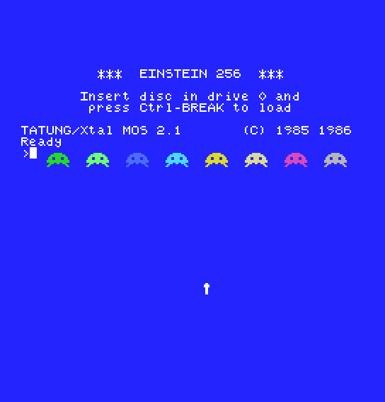
MOS's start-up screen, unchanged, with a row of eight invaders just below Ready, each its own colour, marching right and left together. A white missile climbs from the bottom of the screen. Eight invaders on one line: the TC-01 could show only four of them.
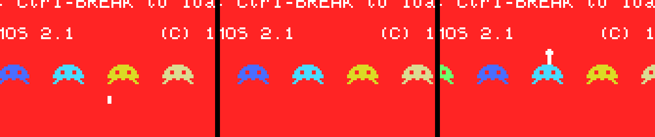
As the missile reaches the row, the whole background turns red, colour 8, because sprite 8 is the ninth on those lines. The missile loses the part of it that shares lines with the row: first its top, then all of it, then only its bottom is missing as it climbs out above. The invaders are drawn whole throughout. When the missile has left the row, the background goes back to blue.
About ten seconds after it starts, the program clears to MOS's 40-column screen and prints the register display.
DEFB 8, 0Ah to g3regs, before the 0FFh. What do you see, and does the background ever turn red?216 to 208, the TC-01's. Nothing new appears on the screen, but something else does change. What, and which entries is the chip now reading?59 before 112) to 216. How many invaders are left, and why those?| Symptom | Cause |
|---|---|
| A diagonal staircase of odd characters instead of sprites | R#0 set to 04h with MOS's R#5 still in place: the tables fall in the name table. Move them |
| One invader missing from the row from the start | It is the backdrop's colour. Against MOS's screen, a sprite in the backdrop colour can't be seen |
| The ninth sprite's number is one too high, or nonsense | Its bits 4-0 were taken from the OR of every read, or from a read without bit 6 |
You can switch the 256 to Graphics 3 over any Graphics II screen and get eight sprites a line. You know where sprite mode 2 looks for its tables: attributes from R#5 (bits 2-0 = 111) and R#11, colours 512 bytes below, patterns from R#6, anywhere in the 128K. You can tell when a ninth sprite dropped out and which one it was, end the list with 216, and hide every sprite with one bit.
S9, Sprites in Many Colours: the colour table you filled with one colour a sprite can give every line its own, and two sprites can share their colours.
