There are various tables in the VDP's VRAM used in Graphics Mode II, used for storing pixel data in the form of tiles on the screen, sprite patterns, sprite attributes and so on. These tables are at default locations in Graphics Mode II but they can be altered if needed via the VPD's registers.
The tables and their locations in the VDP's VRAM are as follows:
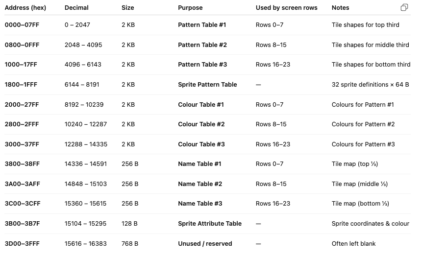
Note: Notice that there are three pattern tables for tile graphics, so if you want to reuse tiles across the three thirds of the screen then you have to write them in each table.
When you write to the Einstein’s video RAM, you must tell the VDP the address you want to use. Because the VDP has only an eight-bit data port, you send the address in two steps through port 9. The first byte is the low part of the address, and the second byte is the high part of the address mixed with two control bits that tell the chip what kind of access you want.
Bit 7 of the second byte must be zero whenever you are talking to VRAM rather than the internal VDP registers. Bit 6 selects the direction of transfer: zero means you intend to read, one means you intend to write. The lower six bits (bits 5–0) of that same byte hold the upper six bits of the VRAM address (A13–A8). Together these two bytes give a full fourteen-bit address, enough to reach any location in the VDP’s 16 K bytes of memory.

Let’s take the example of writing to address 0x1800 (which is 6144 decimal).
The binary representation of that address is 0001 1000 0000 0000.
The lower eight bits, 0000 0000, become the first byte you send (value 0).
The upper six bits, 011000, become part of the second byte, but with bit 6 set to 1 for write and bit 7 left 0 for VRAM access. That produces 01011000 binary, which is 0x58
hex or 88 decimal. So the pair you send to port 9 is 0 then 88. After that, any byte you output to port 8 goes into VRAM starting at 0x1800.
If you instead wanted to start at address 0x0000 (0 decimal), the upper bits would all be zero, so the second byte would be 01000000 binary = 0x40 hex = 64 decimal. Likewise, to reach 0x3B00 (15104 decimal) you would send a second byte of 01110110 binary = 0x76 hex = 118 decimal.
The pattern is always the same:
So for example, to write a sprite pattern into the Sprite Pattern Generator Table we need to send the address 6144, as that is the start of the table as shown above
In Binary 6144 is 0001 1000 0000 0000
The first two bits are control bits, and bit 6 needs to bet set to state we want to write to VRAM.
So the two bytes together would be 0101 1000 0000 0000
The low byte is 0000 0000 (0)
The high byte is 0101 1000 (88)
The assembly to send these two bytes is:
     LD A,0       ; Low Byte
     OUT (9),A
     LD A,88      ; High Byte
     OUT (9),A