In this lesson, you’ll learn how to talk directly to the VDP using Z80 assembly. You’ll switch the machine into a graphics mode, set the screen colours, clear the screen memory, and plot your first pixels, the building blocks of all future graphics programming.
The Z80 CPU talks to hardware devices like the VDP through I/O ports. The two essential instructions are:
OUT (n), A — Send the value in register A to port n.IN A, (n) — Read from port n into register A.The VDP uses two ports on the Einstein:
All interactions follow the same pattern:
The VDP has eight registers that can be sent configuration instructions, such as enabling a specific screen mode, detecting collisions, setting sprite size, and so on.
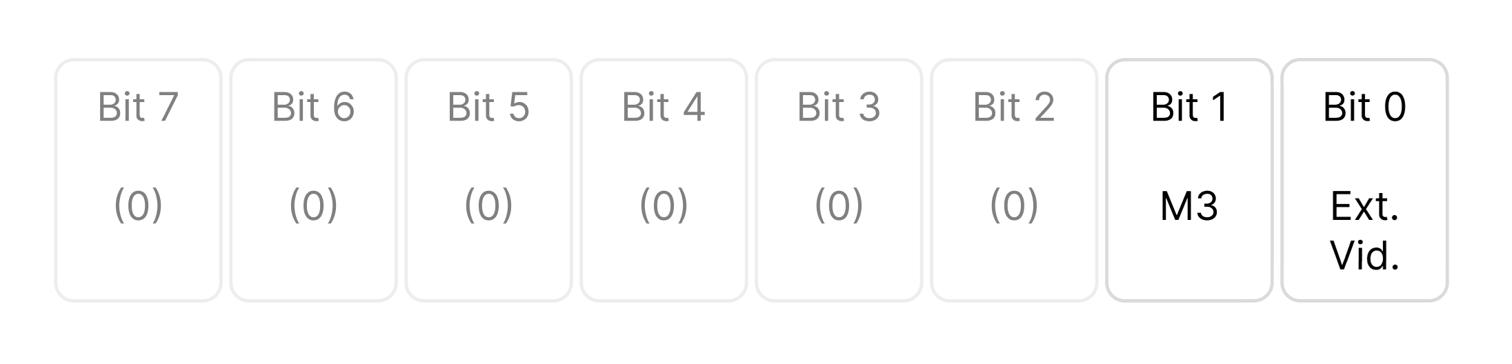
This register contains two active control bits used by the VDP. All other bits (2-7) are reserved for future use and should always be written as zero.
Bit 0 – External Video Enable (EV) Determines whether external video input is displayed.
When set, it tells the VDP to stop generating its own internal video output (the graphics display it normally produces) and instead pass through an external video signal that can be fed into the VDP’s “EXTVDP” pin.
Essentially, it turns the chip into a video overlay processor — you can mix or switch between the VDP’s graphics and another composite video source.
This feature was intended for:
Bit 1 – Mode Bit 3 (M3) One of three mode-selection bits that define the current display mode of the VDP.
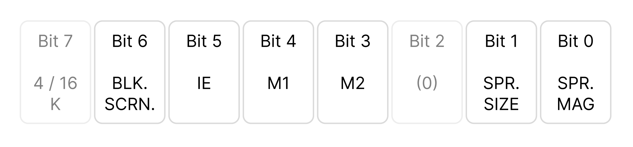
Register 1 contains seven active control bits that configure various aspects of the Video Display Processor’s (VDP) operation. Bit 2 is reserved for future use and must always be written as 0.
Bit 7 – VRAM Size Select
This bit determines which type of video RAM (VRAM) the VDP will use.
On the Tatung Einstein, this bit is always set to 1, since the system uses 4116 DRAMs for its 16K VRAM.
Setting this bit incorrectly will cause the display to malfunction or fail to initialise.
Bit 6 – Display Enable (BLANK)
Controls whether the active display area is shown or blanked out.
When the display is blanked, the screen border remains visible but all sprite and pattern data are suppressed.
This can be used for effects such as:
Blanking does not alter or destroy any video tables in VRAM, and so can't really be used to 'clear the screen' in the traditional sense.
Bit 5 – Interrupt Enable (IE)
Controls the generation of VDP interrupts.
When enabled, the VDP will assert its interrupt output once per frame (during the vertical blanking interval).
This is commonly used to synchronise game logic or animation updates with the video refresh rate.
Bits 4 and 3 – Display Mode Selection (M1 and M2)
These two bits work together with M3 (bit 1 of Register 0) to define which display mode the VDP will operate in. See above.
Bit 2 – Reserved
This bit is unused and must always be written as 0 to ensure future compatibility.
Bit 1 – Sprite Size
This bit determines the basic sprite size.
Setting it to 0 selects 8 × 8 pixel sprites; setting it to 1 selects 16 × 16 pixel sprites.
In 16×16 mode, each sprite pattern number refers to four 8×8 patterns arranged in a square to form a single larger sprite.
Bit 0 – Sprite Magnification
Controls the magnification of all sprites.
With the bit set to 0, sprites appear at their normal size.
When set to 1, each sprite is displayed at double its normal scale — 8×8 sprites become 16×16, and 16×16 sprites become 32×32 on screen.
This feature can be used to simulate zooming or to emphasise large objects without redrawing patterns.
Registers 2 through 6 all perform the same fundamental job:
They define where each of the VDP’s internal data tables begins in VRAM.
Each table holds a specific type of display data, such as tiles, colours, or sprites, and these registers simply tell the VDP where to find them.
Once set, the VDP automatically reads from these locations every frame, so your program doesn’t need to do any ongoing work to maintain them. They are purely setup values that establish the memory layout for the graphics system.
Note: You do not have to explicity configure these, the default values work fine.
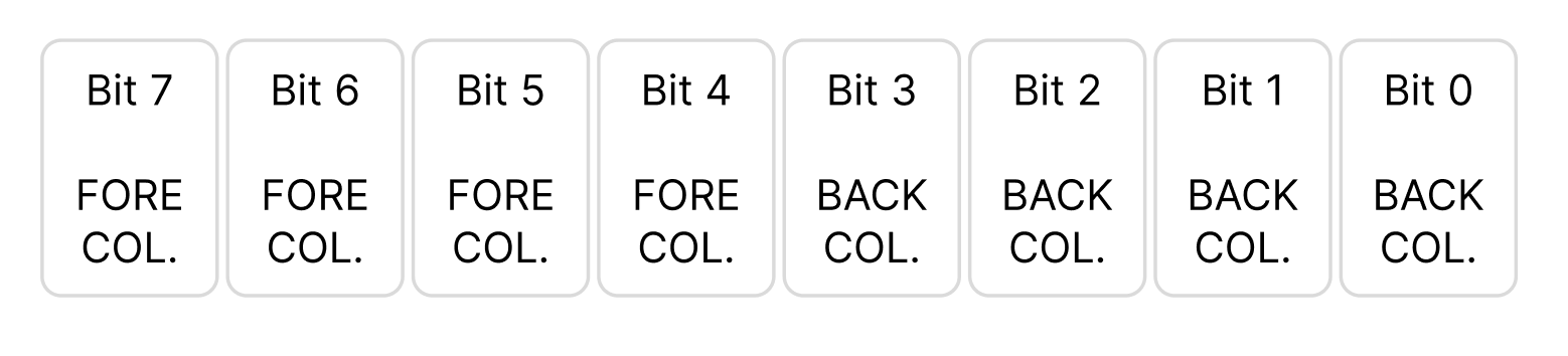
Register 7 controls the overall colour scheme for the screen. It defines two colours, one for the foreground and one for the background, and these values apply globally across all video modes.
Although originally intended for text modes, the same register also affects the appearance of Graphics Mode II, influencing the border, background, and any screen areas where no tile or sprite data is visible.
Register 7 is split into two halves, known as nibbles:
Each colour nibble represents a value between 0 and 15, selecting from the VDP’s 16-colour palette.
The value written to Register 7 is therefore a single byte combining both colours:
Register 7 = (Foreground × 16) + Background
For example, the value 240 (0xF0) gives:
This produces a white-on-black screen.
Register 8 is a read-only status register used to check the VDP’s internal state.
Unlike the previous registers (0–7), which configure how the display operates, this register provides feedback about what the VDP is currently doing.
It cannot be written to — only read — and is mainly used for synchronising code with the video hardware or detecting sprite behaviour.
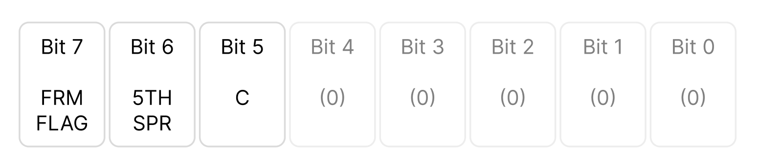
This register reports several useful flags that describe the VDP’s current state.
When you perform an IN from port 1, the byte returned contains these bits:
Bit 7 – Vertical blank flag
Bit 6 – Sprite overflow flag
Bit 5 – Sprite collision flag
Bits 4–0 – Not used (always zero)
When communicating with the VDP, there are two essential write sequences you must use. These define how you change its internal registers and how you set the address in VRAM before writing data.
To set a VDP register, you must always send two bytes:
This tells the VDP, “I’m writing a configuration value to one of your registers.”
To enable graphics mode II we need to configure the M3 bit in register as 1
And enable
In Assembly the instructions for the above are as follows:
; Set Register 0 values
        LD   A,2
        OUT  (9),A
        LD   A,128
        OUT  (9),A
        ; Set Register 1 values

        LD   A,224
        OUT  (9),A
        LD   A,129
        OUT  (9),A
The Video Display Processor (VDP) controls every aspect of the Einstein’s video system, from screen modes and colours to sprite behaviour. The Z80 communicates with the VDP through two ports: one for control and one for data.
Registers 0 and 1 configure the system mode and screen behaviour, enabling Graphics Mode II, display control, and sprite sizing.
Registers 2 to 6 define the positions of the VDP’s internal tables in VRAM — Name, Colour, Pattern, and Sprite tables. These determine where the VDP finds its graphics data, but in most cases the default addresses are ideal and rarely need to be changed.
Register 7 sets the global colour scheme, defining the foreground and background colours used across the screen, border, and blank areas.
Finally, Register 8 is read-only and reports the VDP’s current status, providing flags for vertical blanking, sprite overflow, and collision.
Together, these registers define how the display looks and behaves. Once configured, the VDP automatically manages all on-screen updates, leaving the CPU free to focus on game logic and animation.