← Back to Guides
Build and Installation of the Einstein TC-01 Joystick Interface
Version:
1
November 6, 2026
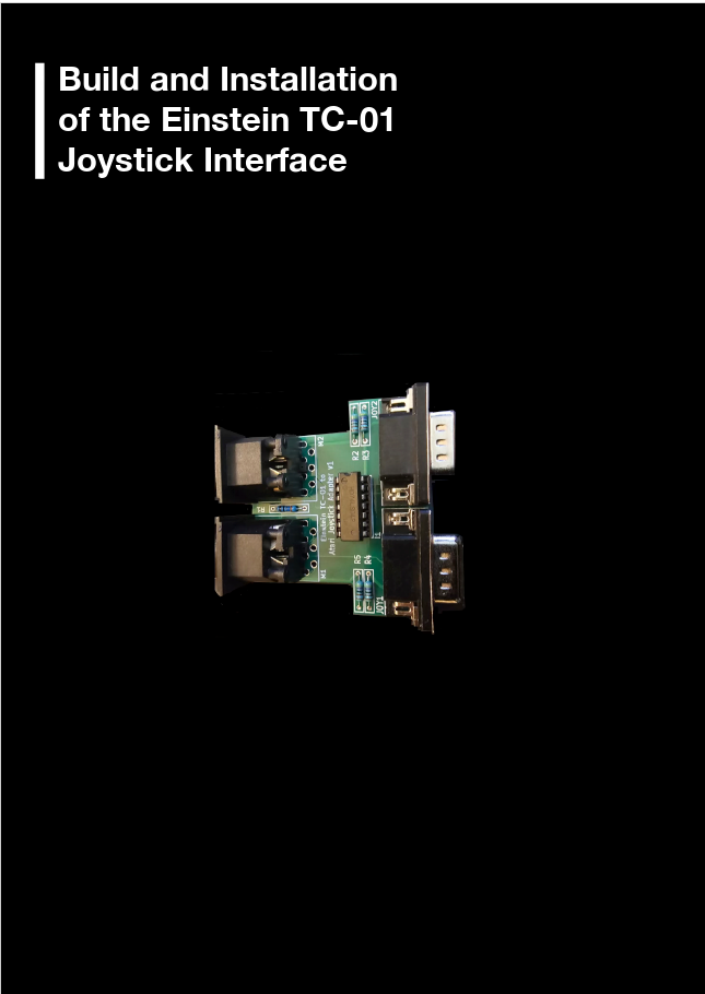
The Einstein TC-01 has recently received a whole host of new hardware expansion and upgrade boards from the Board-Folk team. One of them, the joystick interface, solves a problem that has plagued Einstein users for years: it provides a reliable way of connecting Atari style (DB9) joysticks.
I wrote this guide after building the board and fitting it to no fewer than three TC-01s. I mention that mainly to make the point that building this board is very possible.
When you have finished, your Einstein TC-01 will have a dual joystick adapter: two 7 pin DIN leads connect it to the Einstein, and it gives you two Atari style (DB9) joystick ports.
The Board-Folk team's GitHub page, with this and their other Einstein TC-01 upgrades, is Board-Folk/Einstein-TC-01 Expansions.
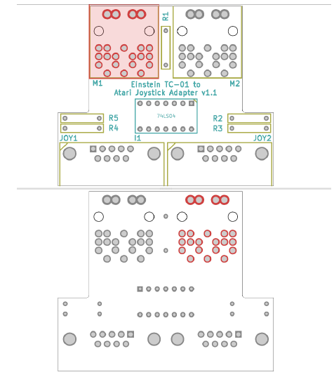
First, with your machine turned off, connect the 7 pin DIN leads to the Einstein TC-01, then connect their other ends to the joystick board. If you plan to use only one joystick port, make sure it is the one marked JOY 1 on the board.
Now connect your Atari style joystick to port one on the board and turn your machine on. I am assuming at this point that you have a Gotek fitted; if you are still using discs the process is the same, although it will take a lot longer and you may not have the games I suggest.
With the machine running, load Dr Frankie, one of the games that is ideal for calibrating the joystick. When it has loaded, select joystick from the options and start the game. If all is working as it should you will have control of the character, but when you let go of the joystick he runs off to the left or right. This is why the board needs calibrating.
With the game running, use a small screwdriver to adjust the screw on top of the variable resistor. You may need to turn it several times to the left, then come back and go several times to the right. Eventually your character will run left or right more slowly; keep going, and in the end he will stop running on his own.
That is the first part of the calibration done. Now run Fruckles and repeat the exercise if the character is still moving on his own. You are now in fine calibration, so do not go mad turning the screw. When it is working as it should, go back to Dr Frankie: if he is still behaving himself, you are finished.
As you go through other games that use joysticks, if you notice any peculiar behaviour, repeat the calibration for that game, then go back to the two games above and make sure all is still well.
Note: in Oh Mummy the character always returns to the bottom left when you let go of the joystick, so do not calibrate using that game.
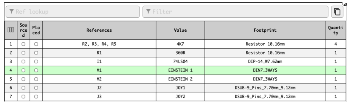
From Board-Folk's TC01AtariJoystick, where the up-to-date list is kept. Remember that R1 is replaced by the 1K variable resistor, and that the two 7 pin DIN male to male cables are not on the list.

This form is protected by reCAPTCHA, and the Google Privacy Policy and Terms of Service apply.
