Games require more than single key presses. Players must be able to:
The MCAL input routines (KEYIN, ZGETLIN, etc.) are not suitable for this. They block, pause execution, or return only a single key.
To achieve real-time control, you must read the keyboard matrix manually.
This is done using the AY-3-8910’s two I/O ports.
Before we examine the code, we will explain the matrix system and how it works on the Einstein.
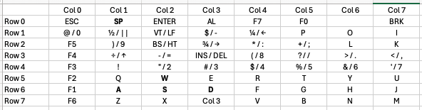
The keyboard is arranged electrically as an 8×8 grid:
A full scan consists of:
The Einstein keyboard is wired as active-low:
This is important: a pressed key shows up as a 0 bit in the column byte.
We will use this behaviour in both example programs.
The Einstein uses the AY-3-8910 not only for sound, but also for keyboard I/O.
It has two ports:
These are accessed through I/O ports:
Before scanning, register 7 must be set so:
This is achieved with:
LD A,7
OUT (2),A
LD A,127
OUT (3),A
Bit 7 = 0 → Port A output
Bit 6 = 1 → Port B input
Rows are selected by writing a byte with exactly one 0 bit.
Example pattern:
RowByte (binary)Byte (decimal)011111110254111111101253211111011251311110111247411101111239511011111223610111111191701111111127
The example programs use RLC C to rotate the zero bit through all 8 positions.
After selecting a row via Register 14, you select Register 15:
LD A,15
OUT (2),A
IN A,(2)
The value returned in A contains 8 bits:
Because each row can hold as many as 8 keys, you must read all 8 rows to know whether any key is pressed.
The full key-to-row and key-to-column mapping is included in the appendix at the end of this module.
The appendix includes:
You will use this table frequently when designing controls.
For now, we will move on to the example programs.
This first program:
This is invaluable for debugging — you can hold keys and watch the pattern change.
ORG 256

; Set Up Input/Output Ports

    LD A,7
    OUT (2),A
    LD A,127
    OUT (3),A

; Begin scanning

    LD C,254                ; Load 11111110 Into register C, Selecting row 0
    LD HL,64485             ; Establish HL as address at memory space 64485

    LD E, 8                 ; Set Counter for eight rows

; Scan all keyboard rows

ScanLoop:
    LD A,14                 ; Select Register 14
    OUT (2),A               ; Send to Port 2
    LD A,C                  ; Load C, the binary for row 0, into A
    OUT (3),A               ; Send row 0 to Port 3
    LD A,15                 ; Select Register 15
    OUT (2),A               ; Send to Port 2

    IN A,(2)                ; Read values from Port 2 in to A (The key pressed as a byte value)
    LD (HL),A               ; Write value in A into HL

    CALL PrintBits          ; Print the byte to screen

    LD A, 13                ; New line
    RST 8
    DEFB 158
    LD A, 10
    RST 8
    DEFB 158

    INC HL                  ; Move HL to the next byte ready for next values
    DEC E
    LD A, E
    CP 0
    RET Z
    RLC C                   ; Rotate the C byte left so the new row is selected
    JR ScanLoop             ; Continue loop until the carry flag is not set

; A = value to print as binary

PrintBits:
    LD B,8                  ; 8 bits to print

BitLoop:
    RLC A                   ; rotate left, bit 7 -> carry
    LD D,A                  ; save current value
    LD A,'1'
    JR C,PrintIt
    LD A,'0'

PrintIt:
    RST 8
    DEFB 158
    LD A,D
    DJNZ BitLoop
    LD A,' '               ; space after the byte
    RST 8
    DEFB 158
    RET

RET
This program uses matrix scanning to control a sprite in Graphics Mode II.
It demonstrates:
ORG 256
; -----------------------
; Enable Graphics Mode II
; -----------------------
; Set Register 0 Values
      LD   A,2
      OUT  (9),A
      LD   A,128
      OUT  (9),A
; Set Register 1 Values (16x16 sprites)
      LD   A,226
      OUT  (9),A
      LD   A,129
      OUT  (9),A
; --------------------------
; Fore / Back Global Colours
; --------------------------
      LD   A, 240        ; 11110000 (white,black)
      OUT  (9), A
      LD   A, 135
      OUT  (9), A
; -----------------
; Write Blank Tiles
; -----------------
; Top Third Blank Tile
      LD   A, 0
      OUT  (9), A
      LD   A, 64
      OUT  (9), A
      LD A, 0
      OUT (8), A
      OUT (8), A
      OUT (8), A
      OUT (8), A
      OUT (8), A
      OUT (8), A
      OUT (8), A
      OUT (8), A
; Middle Third Blank Tile
      LD   A, 0
      OUT  (9), A
      LD   A, 72
      OUT  (9), A
      LD A, 0
      OUT (8), A
      OUT (8), A
      OUT (8), A
      OUT (8), A
      OUT (8), A
      OUT (8), A
      OUT (8), A
      OUT (8), A
; Bottom Third Blank Tile
      LD   A, 0
      OUT  (9), A
      LD   A, 80
      OUT  (9), A
      LD A, 0
      OUT (8), A
      OUT (8), A
      OUT (8), A
      OUT (8), A
      OUT (8), A
      OUT (8), A
      OUT (8), A
      OUT (8), A
; --------------------------------
; Clear Name Table with Blank Tile
; --------------------------------
      LD A, 0
      OUT (9), A
      LD A, 120
      OUT (9), A
LD BC, 768 ; Set Counter for table address space
ClearLoop:
      LD A, 0
      OUT (8), A
      DEC BC
      LD A, B
      OR C
      JP NZ, ClearLoop
; ----------------------
; Define Sprite Patterns
; ----------------------
      LD A,0
      OUT (9),A
      LD A,88
      OUT (9),A
; Player Sprite
      LD A,%01111110 : OUT (8),A
      LD A,%10000001 : OUT (8),A
      LD A,%10111101 : OUT (8),A
      LD A,%10100101 : OUT (8),A
      LD A,%10100101 : OUT (8),A
      LD A,%10111101 : OUT (8),A
      LD A,%10000001 : OUT (8),A
      LD A,%01111110 : OUT (8),A
; --------------
; Main Game Loop
; --------------
MainLoop:
      CALL UpdatePlayerSprite
      CALL CheckKeys
      JP MainLoop
UpdatePlayerSprite:
      LD A,0
      OUT (9),A
      LD A,123
      OUT (9),A
; Player Sprite
      LD A,(PlayerSpriteY)
      OUT (8),A
      LD A,(PlayerSpriteX)
      OUT (8),A
      LD A,0
      OUT (8),A
      LD A,15
      OUT (8),A
RET
CheckKeys:
CALL Delay
    ; W Pressed
    LD C, 223               ; Move to row 5, 11011111
    CALL ReadRow
    BIT 5, A
    CALL Z, WPressed
    ; A Pressed
    LD C, 191               ; Move to row 6
    CALL ReadRow
    BIT 6, A
    CALL Z, APressed
    ; S Pressed
    CALL ReadRow
    BIT 5, A
    CALL Z, SPressed
    ; D Pressed
    CALL ReadRow
    BIT 4, A
    CALL Z, DPressed
RET
ReadRow:
    LD A,14                 ; Select Register 14
    OUT (2),A               ; Send to Port 2
    LD A,C                  ; Load C, the binary for row 5, into A
    OUT (3),A               ; Send row 5 to Port 3
    LD A,15                 ; Select Register 15
    OUT (2),A               ; Send to Port 2
    IN A,(2)                ; Read values from Port 2 in to A (The key pressed as a byte value)
RET
WPressed:
      LD A, (PlayerSpriteY)
      DEC A
      LD (PlayerSpriteY), A
RET
APressed:
      LD A, (PlayerSpriteX)
      DEC A
      LD (PlayerSpriteX), A
RET
SPressed:
      LD A, (PlayerSpriteY)
      INC A
      LD (PlayerSpriteY), A
RET
DPressed:
      LD A, (PlayerSpriteX)
      INC A
      LD (PlayerSpriteX), A
RET
Delay:
      LD BC,3000      ; adjust this number for smooth speed
DLoop:
      DEC BC
      LD A,B
      OR C
      JP NZ,DLoop
      RET
; ---------
; Variables
; ---------
PlayerSpriteY:
       DEFB 50
PlayerSpriteX:
       DEFB 50
JP $ ; JP Idefinitely
(Your exact supplied listing will be placed here, unchanged.)