
The Z80 PIO
Introduction
This article like many others I will be doing, is a recreation, tidy up, etc of articles originally published in old User Group Magazines. As the quality of these old magazines is quite poor, I decided to take it upon myself to recreate those articles and present them in an improved format, with pictorial enhancements and where possible improved content.
This article was originally written by Dave Harvey and Published in Einstein Monthly News Volume1 Issue 3
The Article
In writing this article I have had to assume the reader has a knowledge of m/c code, this is necessary since interrupts are involved which need to be handled in m/c code.
The Z80 PIO chip has two "sides" on one side is port A, which is used for the printer port, and on the other port B, which is the user port. They are more or less the same to the programmer, however port B may directly drive Darlington Transistors, this is useful for control purposes.
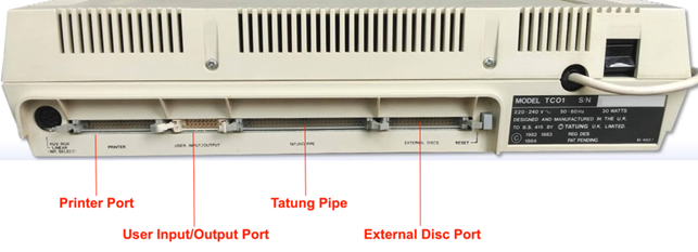
The pinnouts for the port are shown in the back of the Einstein Intro Book (page 218 in mine). There are 8 data lines (DO - D7), a data ready line (RDY) and a strobe line(STB) the rest are either +5 or 0 volts. It must be stressed that any experimenting must of course be done with great caution as not only could the user port be damaged but the printer port would also go being part of the same chip! Having Said that it is as well to have a use for the port or it’s pointless being able to program it, so if your not to up on wiring up a transistor or two or using logic I.C.s then beware and get someone to help. The uses I have put mine to are a link to my Dragon 32 and to run a speech synth’, although I must admit In ever use either of then, all the fun was finding out how.
The PIO can be programmed in any one of 4 modes, they are:
OUTPUT MODE (0)
INPUT MODE (1)
BIDIRECTIONAL MODE (2)
CONTROLMODE (3)
Mode 2 can only be used with port A due to it requiring both side A and side B handshake (STB and RDY) lines and since port A is the printer port there is little point in going into this mode to deeply.
I’d better first explain what Handshakes are, they are simply Signals sent on the RDY and STB lines to force order into the passing of data from PIO to peripheral and back. Here is what happens with theZ8O PIO, first in mode 0, when data is sent to port &32, the RDY line will go from low to high to tell the peripheral device that data is awaiting its attention (on the 8 data lines) when the device sees this and reads the data it will lower and then raise the STB line to say the data has been taken. At this point the PIO will lower its RDY line and this cycle may then be repeated to send the next byte. The sequence for mode 1 is as follows, the peripheral device will lower and then raise the STB line to say it has data for the PIO and the PIO will lower its RDY line to say it is busy taking the data, when it does in fact take the data the ready line will return ta high and the cycle is complete and may be repeated. Although the Interrupt, which is generated by the rising STB line in both cases has not yet been mentioned these are the handshake sequences for the input/output modes 0 and 1.
It is important to note that these handshake sequences are not suitable, as they are, for Centronics type operation, as the Z80 PIO doesn’t follow the normal protocol of waiting for the device to become ready and then sending the data followed by a strobe it in fact does it backwards to the other chips I]have programmed, the Motorola 6821 PIA and the 6522 VIA which, especially the later, are programmable to suit the peripherals requirements. The Einstein has an extra chip added to port A to make the handshake logic appear the other way round, this is what I had to do with the speech synth chip which was made to require the Centronics type sequence.
Remaining with modes0 and 1 I will now go on to the interrupts which are as I said before generated when the strobe line goes up. The Z80 PIO is used via interrupts, in order to explain how it all works, we will stick with output mode (0) for now, and go through the procedure for setting the port up for that mode and sending a byte of data.
The first thing we should do before setting up the port is to get our interrupt routine in position and the vector at address FB 12/ 3 pointing to it. The interrupt routine may do one of two things, it may handle the sending of data from a file on it's own or it may simply set a flag in memory to tell us that a strobe has been received and therefore that the peripheral is ready for the next byte(this would be like polling). We will choose the simpler f the two, the latter.
The routine looks like this:
INTRPT:PUSH AF
LD A, 1
LD (FLAG), A
POPAF
EI
RETI
This routine would be the same for input and output note that all reg's used must be preserved as the Z80 doesn't do this for us, also the interrupts are re-enable on exit from the routine (EI). Because this is an interrupt all our program needs to do is clear the flag, send the data to the port and then check the flag to see if the data has been taken yet. So, we have our interrupt routine in position and are ready to set up the vector and the port here is a routine to do it:
PIOOUT: PUSH HL
PUSH AF
LD HL, INTRPT
LD (FB12), HL
LD A, 12H
OUT(33H) , A
LD A, OFH
OUT(33H), A
LD A, 87H
OUT(33H), A
POPAF
POPHL
RET
You can see that 3bytes have been sent to the port B port control register, the first is the ports half of the interrupt vector address the higher half is supplied by theZ80 I register (it's already set to FB) so when the interrupt is called we Whole address FB12, FB supplied by the I register and the 12 supplied by the port, bit 0 is always 0 to tell the port that this is the vector byte. The next byte is the mode, actually bits 6 and 7 contain the mode, bits 0 , 1 , 2and 3 are all set to 1, this tells the port that this is the mode byte, bits 4 and 5 are unused and I have set them to0. The next byte is the interrupt control byte, bit 7 set enables interrupts, bits 0 , 1 , 2 and 3 tell the port that this is the interrupt control byte. The port is now set up to send data to a peripheral which can use it's handshake logic all we do is clear the flag, send our data via an OUT instruction to the port B data register 32H and wait for the flag to go non zero signifying that the data has been taken. Here is a routine to send a byte in mode 0:
SEND: PUSH AF
LD A,0
LD (FLAG) , A
POPAF
OUT(32H) , A
POLL: LD A, (FLAG )
CP O
JRZ, POLL
RET
The data is expectedto be in A.
Now on to input mode1. First the handshake sequence, this starts by the peripheral sending a strobe(down then up on the STB line) to tell our PIO that data is ready to be read ,and as we have seen this causes an interrupt, the PIO then puts it's ready line down to show i t is busy and cannot take any communications, when we finally read the port this will cause the ready line to rise telling the peripheral that we are ready for a further byte. The interrupt routine is as for mode 0.The setup routine is as follows:
PIOIN: PUSH HL
PUSH AF
LD HL, INTRPT
LD (FB12), HL
LD A,0
LD (FLAG), A
OUT ( 33H), A
LD A, 4FH
OUT(33H) , A
LD A, 87H
OUT ( 33H), A
POPAF
POPHL
RET
You can see that it's almost the same as for mode 0 except the byte (the second) is of course different, and the FLAG byte is set to 0 so as to be immediately ready before any data can arrive. The routine to read the port is as follows:
READ: LD A, (FLAG )
CP 0
JR Z, READ
LD A, 0
LD (FLAG), A
IN A, (32H)
RET
The routine begins by polling the flag (remember this was initially cleared by the setup routine),when it goes non zero the flag is cleared and the port read. This concludes the section on modes 0 and 1.
The next section isa brief rundown on mode 2, the bi directional mode. It is unusable from the chip in the Einstein due to requiring all four handshake lines and since not only are port A lines tied up with the printer, they are tampered with to make them work as a centronics port. Mode 2 Is designed to work as both input and output from side A of the port it is a combination of mode 0 and mode 1 logic with port A handshake lines used for output control and port B handshake lines used for input control, the logic on them is identical to that o f mode 0 and 1 except that data is only be allowed out when the STB line is low and the peripheral should only output data when it lowers its STB this avoids contention on the data lines.
When using this mode, port B must be set to mode 3 with its mask register set to inhibit all bits (don't panic mode 3 is next), this is because the same interrupt vector is returned for both modes so you should operate mode 3 in polled mode when port A i s in mode 2.
Now for mode 3operation this mode is designed around control applications it doesn't use handshakes (although it does effect the ready lines), it can be setup so that some of the 8 data lines can be input and the others output the port can be written to or read from at any time and interrupts if enabled will be generated after a change in the state of the register has occurred, and a logic function(OR or AND) has produced a true result. This mode does take a little more though to set up than the other modes but it will probably be the mode which most people will find easiest and best to play around with. I shall go through the control bytes to be sent to the port (&33) and what they do.
The first byte as with the other modes sets the mode and bits 0, 1 , 2 and 3 are set to is bits 4and 5 don't matter and bits 6 and 7 make the mode number making the first byte CF to set up the mode.
The next byte must be the input/output select byte which determines which of the data lines will be input and which will be output a 1 selects input therefore if we send 49H(00101001) lines 0 , 3 and 5 will be inputs and the rest outputs.
The next byte must be the interrupt vector and as with the other modes bit 0 must be set to 0,this is the same as for the other modes, it provides the lower half interrupt vector address.
The next byte is the interrupt control byte bits 0 , 1 , 2 and 3 are set to 7 to signify this, bit 7 as with the other modes is interrupt enable (1 = enabled) bit 6 is a new one it selects the logic t o be used OR (0)or AND (1) i f OR is selected then if any of the monitored bits change to the active level (selected by bit 5 ) an interrupt will be requested. If AND is selected all the monitored bits must change to the active state of the monitored lines (high or low). Bit 4 tells the chip if a mask byte follows (1=yes).
The next byte (if bit 4 of the previous byte was 1) must be the mask. This masks off any unused bits if the mask is D6 (11010110) then only bits 0 , 3 and 5 will be monitored.
Setting the interrupt vector is as before at FB12. If for example the active state is set to high and the logic is OR, an interrupt will be generated if any of the monitored lines goes high. Your interrupt routine must read the data from the port and take any action your application requires an example might be a sensor requesting a light on the sensor would be connected to an input line and the light switch to an output line so that you then send a 1 to that bit to turn on the light.
Really at this point even the manual stops because the next action really depends on your application you may only need to send a byte to the port data register (32h) or you may need to reset the port completely for a new test. If you don't enable the interrupts the data register may be polled this may be easier to start with.
If you intend to use the port, I would at least buffer the lines through something like a simple buffer I.C. good luck D.A.Harvey